
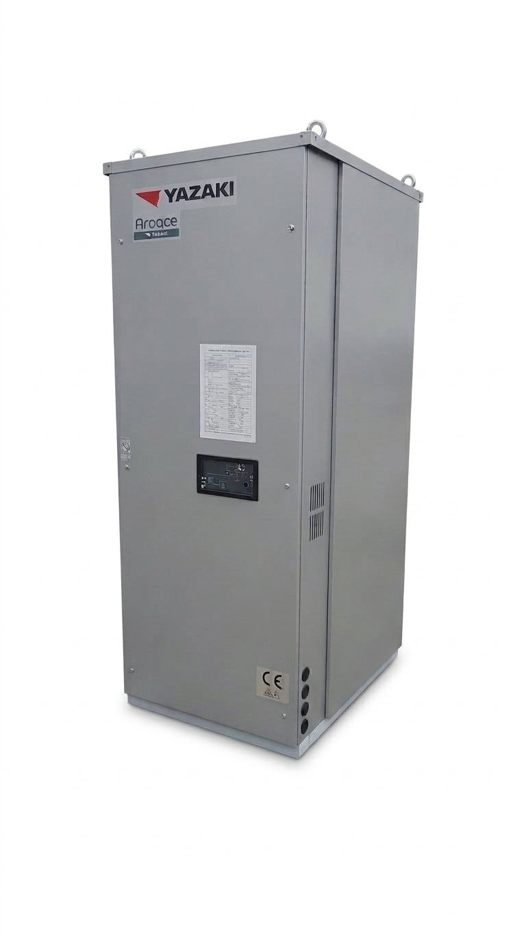
Yazaki
Yazaki WFC-SC
Hot water-driven single-effect absorption chillers
- Cooling capacity
- 17.6 – 176 kW
- Energy
- Hot water
- Efficiency
- COP: 0.7
Thermax · Absorption chillers
Gas-fired double-effect absorption chillers
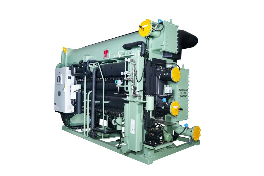
Technical data
Models
Technical data from the manufacturer's data sheet.
| Model | Unit | G2 C3 | G2 C4 | G2 D1 | G2 D2 | G2 D3 | G2 D4 | G2 E1 | G2 E2 | G2 E3 | G2 E4 | G2 E5 | G2 E6 | G2 F1 | G2 F2 | G2 F3 | G2 G1 | G2 G2 | G2 G3 | G2 G4 | G2 G5 | G2 G6 |
|---|---|---|---|---|---|---|---|---|---|---|---|---|---|---|---|---|---|---|---|---|---|---|
| GENERAL DATA | ||||||||||||||||||||||
| Version / application | Direct-fired double-effect absorption chiller (natural gas / LPG / diesel) | |||||||||||||||||||||
| Installation location | Indoor | |||||||||||||||||||||
| Refrigerant / absorbent | Water (R718) / Lithium bromide (LiBr) | |||||||||||||||||||||
| Nominal COP | 1.5 | |||||||||||||||||||||
| Chilled water inlet / outlet temperature | °C | 12.0 / 7.0 | ||||||||||||||||||||
| Cooling water inlet / outlet temperature | °C | 32.0 / 37.1 | ||||||||||||||||||||
| Accepted fuels | Natural gas, LPG, propane, diesel, kerosene, biogas | |||||||||||||||||||||
| Maximum allowable pressure, water circuits | bar(g) | 8 | ||||||||||||||||||||
| CAPACITY AND HYDRAULIC CIRCUITS | ||||||||||||||||||||||
| Nominal cooling capacity | kW | 400.9 | 502.9 | 640.1 | 759.6 | 942.5 | 1,065.6 | 1,269.6 | 1,410.3 | 1,614.2 | 1,772.5 | 1,937.8 | 2,159.3 | 2,307.1 | 2,391.5 | 2,665.8 | 3,017.5 | 3,383.2 | 3,734.9 | 4,051.4 | 4,575.4 | 4,969.3 |
| Nominal cooling capacity (reference) | TR | 114 | 143 | 182 | 216 | 268 | 303 | 361 | 401 | 459 | 504 | 551 | 614 | 656 | 680 | 758 | 858 | 962 | 1,062 | 1,152 | 1,301 | 1,413 |
| Chilled water flow | m³/h | 68.8 | 86.3 | 109.8 | 130.3 | 161.7 | 182.8 | 217.8 | 241.9 | 276.9 | 304 | 332.4 | 370.4 | 395.7 | 410.2 | 457.2 | 517.6 | 580.3 | 640.6 | 694.9 | 784.8 | 852 |
| Chilled water connection diameter | DN | 125 | 125 | 150 | 150 | 200 | 200 | 200 | 250 | 250 | 250 | 250 | 300 | 300 | 300 | 300 | 350 | 350 | 350 | 350 | 350 | 350 |
| Cooling water flow | m³/h | 114 | 143 | 182 | 216 | 268 | 303 | 361 | 401 | 459 | 504 | 551 | 614 | 656 | 680 | 758 | 858 | 962 | 1,062 | 1,152 | 1,301 | 1,413 |
| Cooling water connection diameter | DN | 150 | 150 | 200 | 200 | 250 | 250 | 250 | 300 | 300 | 300 | 300 | 350 | 350 | 350 | 350 | 400 | 400 | 400 | 400 | 450 | 450 |
| FUEL AND FLUE GAS CIRCUIT | ||||||||||||||||||||||
| Natural gas consumption (NCV = 9,000 kcal/Nm³) | Nm³/h | 26 | 32.5 | 41.2 | 49 | 60.4 | 68.5 | 81.4 | 90.6 | 103.8 | 114 | 124.5 | 138.7 | 147.7 | 154.5 | 171.9 | 194.4 | 217.2 | 239.6 | 260.5 | 293.2 | 319.1 |
| Diesel / oil consumption (NCV = 10,200 kcal/kg) | kg/h | 22.9 | 28.6 | 36.4 | 43.2 | 53.3 | 60.4 | 71.8 | 80 | 91.6 | 100.6 | 109.9 | 122.4 | 130.4 | 136.3 | 151.8 | 171.4 | 191.7 | 211.5 | 229.9 | 258.8 | 281.6 |
| Flue gas chimney connection diameter | DN | 150 | 150 | 200 | 200 | 250 | 250 | 250 | 300 | 300 | 300 | 300 | 350 | 350 | 350 | 350 | 400 | 400 | 450 | 450 | 450 | 450 |
| ELECTRICAL DATA | ||||||||||||||||||||||
| Solution pump motor power | kW | 2.2 | 2.2 | 2.2 | 2.2 | 3 | 3 | 3 | 3.7 | 3.7 | 3.7 | 3.7 | 5.5 | 5.5 | 5.5 | 6.6 | 6.6 | 6.6 | 7.5 | 7.5 | 9 | 9 |
| Solution pump current | A | 6 | 6 | 6 | 6 | 8 | 8 | 8 | 11 | 11 | 11 | 11 | 14 | 14 | 14 | 17 | 17 | 17 | 20 | 20 | 27 | 27 |
| Refrigerant pump motor power | kW | 0.3 | 0.3 | 0.3 | 0.3 | 0.3 | 0.3 | 0.3 | 0.3 | 0.3 | 0.3 | 0.3 | 1.5 | 1.5 | 1.5 | 1.5 | 1.5 | 1.5 | 1.5 | 1.5 | 1.5 | 1.5 |
| Refrigerant pump current | A | 1.4 | 1.4 | 1.4 | 1.4 | 1.4 | 1.4 | 1.4 | 1.4 | 1.4 | 1.4 | 1.4 | 5 | 5 | 5 | 5 | 5 | 5 | 5 | 5 | 5 | 5 |
| Vacuum pump motor power | kW | 0.75 | ||||||||||||||||||||
| Vacuum pump current | A | 1.8 | ||||||||||||||||||||
| Maximum burner motor power | kW | 0.8 | 0.8 | 1.5 | 1.5 | 1.5 | 1.5 | 4 | 4 | 4 | 4 | 5.5 | 5.5 | 5.5 | 7.5 | 7.5 | 11 | 11 | 11 | 11 | 15 | 15 |
| Burner motor current | A | 2 | 2 | 3.2 | 3.2 | 3.2 | 3.2 | 8.7 | 8.7 | 8.7 | 8.7 | 11.1 | 11.1 | 11.1 | 14.7 | 14.7 | 21 | 21 | 21 | 21 | 28 | 28 |
| Total electrical consumption | kVA | 9.1 | 9.1 | 11.4 | 11.4 | 17.5 | 17.5 | 19.6 | 19.6 | 21.3 | 21.3 | 26.1 | 26.1 | 28.7 | 28.7 | 30.8 | 35.4 | 35.4 | 39.4 | 39.4 | 44.4 | 44.4 |
| Supply voltage | V / Hz | 415V (±10%), 50Hz (±5%), 3 phases + N | ||||||||||||||||||||
| DIMENSIONS, WEIGHTS AND MAINTENANCE | ||||||||||||||||||||||
| Length (L) | mm | 2,930 | 2,930 | 4,410 | 4,410 | 4,410 | 4,410 | 5,010 | 5,140 | 5,140 | 5,140 | 5,140 | 5,140 | 6,220 | 6,220 | 6,220 | 7,670 | 7,670 | 7,870 | 7,870 | 8,150 | 8,150 |
| Width (W) | mm | 2,460 | 2,460 | 2,780 | 2,780 | 3,080 | 3,080 | 3,130 | 3,420 | 3,420 | 3,420 | 3,650 | 3,650 | 3,760 | 3,760 | 3,760 | 3,830 | 3,830 | 4,260 | 4,260 | 4,780 | 4,780 |
| Height (H) | mm | 2,880 | 2,880 | 2,850 | 2,850 | 3,010 | 3,010 | 3,010 | 3,350 | 3,350 | 3,350 | 3,590 | 3,590 | 3,660 | 3,660 | 3,660 | 3,780 | 3,780 | 4,010 | 4,010 | 4,260 | 4,260 |
| Operating weight | kg | 7,800 | 8,100 | 10,400 | 10,800 | 12,900 | 13,500 | 15,100 | 17,800 | 18,500 | 19,000 | 21,700 | 22,200 | 28,100 | 28,500 | 29,500 | 32,900 | 34,500 | 44,100 | 44,800 | 53,500 | 54,800 |
| Max. shipping weight | kg | 7,300 | 7,600 | 10,000 | 10,300 | 12,700 | 13,200 | 14,800 | 17,100 | 17,700 | 18,200 | 20,600 | 21,000 | 26,500 | 27,000 | 27,900 | 32,800 | 40,900 | 41,300 | 49,800 | 48,500 | 49,500 |
| Tube removal clearance | mm | 2,650 | 2,650 | 3,600 | 3,600 | 3,600 | 3,600 | 4,500 | 4,200 | 4,200 | 4,200 | 4,200 | 4,200 | 5,500 | 5,500 | 5,500 | 6,700 | 6,700 | 6,800 | 6,800 | 7,000 | 7,000 |
Downloads
We'll help you choose the model and send you the technical documentation and a proposal.
Absorption chillers
Yazaki
Hot water-driven single-effect absorption chillers
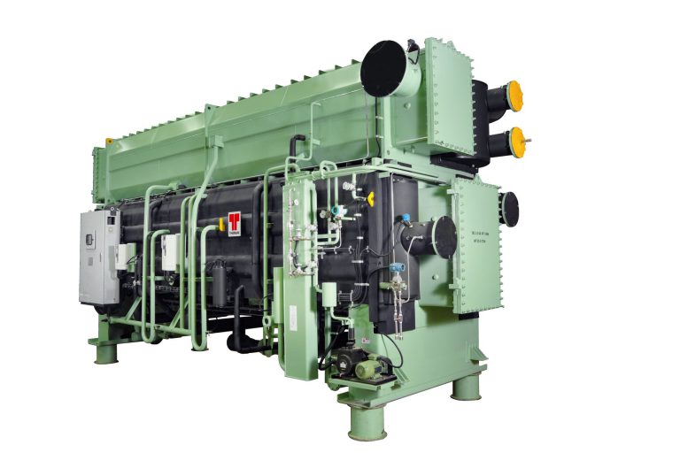
Thermax
Hot water-driven single-effect absorption chillers
Thermax
Hot water-driven single-effect absorption chillers
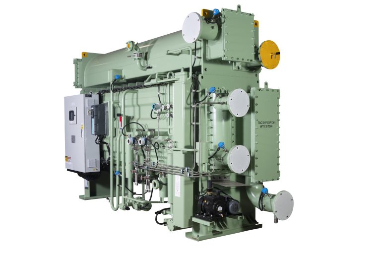
Thermax
Steam-driven single-effect absorption chillers
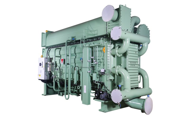
Thermax
Steam-driven double-effect absorption chillers
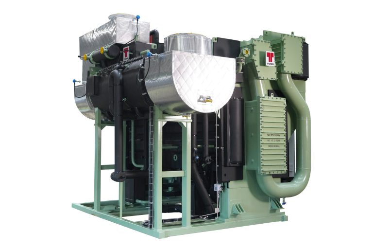
Thermax
Exhaust gas-driven double-effect absorption chillers