
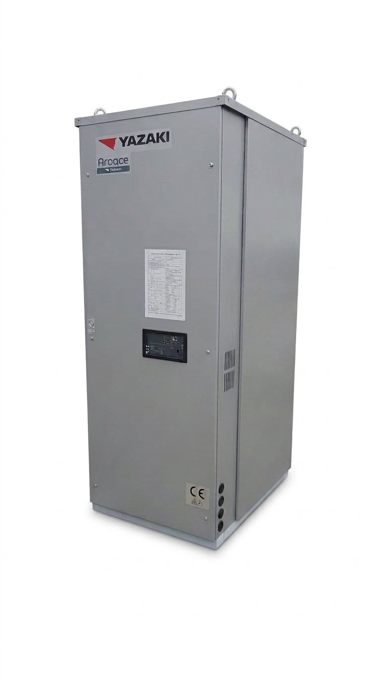
Yazaki
Yazaki WFC-SC
Hot water-driven single-effect absorption chillers
- Cooling capacity
- 17.6 – 176 kW
- Energy
- Hot water
- Efficiency
- COP: 0.7
Thermax · Absorption chillers
Steam-driven single-effect absorption chillers
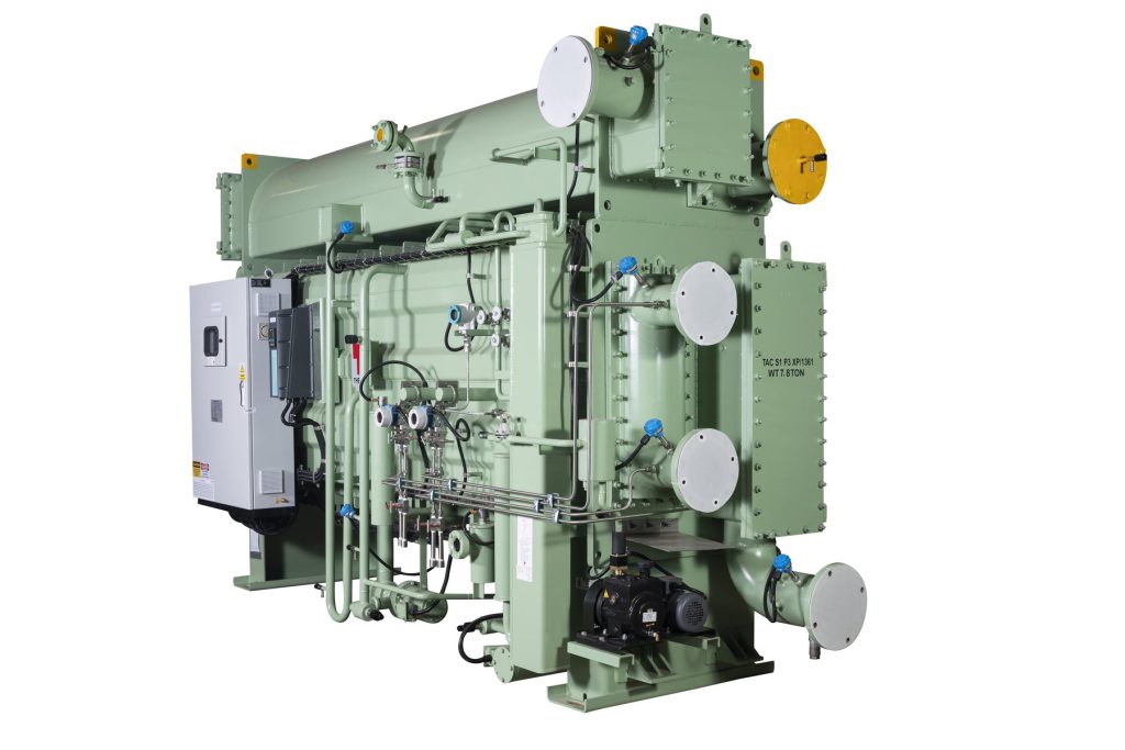
Technical data
Models
Technical data from the manufacturer's data sheet.
| Model | Unit | S1 C3 | S1 C4 | S1 D1 | S1 D2 | S1 D3 | S1 D4 | S1 E1 | S1 E2 | S1 E3 | S1 E4 | S1 E5 | S1 E6 | S1 F1 | S1 F2 | S1 F3 | S1 G1 | S1 G2 | S1 G3 | S1 G4 | S1 G5 | S1 G6 | S1 H1 | S1 H2 | S1 J1 | S1 J2 |
|---|---|---|---|---|---|---|---|---|---|---|---|---|---|---|---|---|---|---|---|---|---|---|---|---|---|---|
| GENERAL DATA | ||||||||||||||||||||||||||
| Version / application | Single-effect absorption chiller driven by low-pressure steam [0.6 - 3.5 bar(g)] | |||||||||||||||||||||||||
| Installation location | Indoor | |||||||||||||||||||||||||
| Refrigerant / absorbent | Water (R718) / Lithium bromide (LiBr) | |||||||||||||||||||||||||
| Nominal COP | 0.8 | |||||||||||||||||||||||||
| Chilled water inlet / outlet temperature | °C | 12 / 7 | ||||||||||||||||||||||||
| Cooling water inlet / outlet temperature | °C | 32.0 / 38.8 | ||||||||||||||||||||||||
| Nominal inlet steam pressure | bar(g) | 1.5 | ||||||||||||||||||||||||
| Maximum allowable steam pressure | bar(g) | 5 | ||||||||||||||||||||||||
| Maximum allowable pressure, water circuits | bar(g) | 8 | ||||||||||||||||||||||||
| CAPACITY AND HYDRAULIC CIRCUITS | ||||||||||||||||||||||||||
| Nominal cooling capacity | kW | 404.4 | 506.4 | 643.6 | 763.2 | 956.6 | 1,072.6 | 1,276.6 | 1,441.9 | 1,649.4 | 1,783 | 1,965.9 | 2,191 | 2,293 | 2,395 | 2,672.8 | 3,021 | 3,386.7 | 3,734.9 | 4,051.4 | 4,575.4 | 4,969.3 | 5,581.2 | 6,326.8 | 6,798.1 | 7,385.4 |
| Nominal cooling capacity (reference) | TR | 115 | 144 | 183 | 217 | 272 | 305 | 363 | 410 | 469 | 507 | 559 | 623 | 652 | 681 | 760 | 859 | 963 | 1,062 | 1,152 | 1,301 | 1,413 | 1,587 | 1,799 | 1,933 | 2,100 |
| Chilled water flow | m³/h | 69.4 | 86.9 | 110.4 | 130.9 | 164.1 | 184 | 219 | 247.3 | 282.9 | 305.8 | 337.2 | 375.8 | 393.3 | 410.8 | 458.4 | 518.2 | 580.9 | 640.6 | 694.9 | 784.8 | 852.3 | 957.3 | 1,085.2 | 1,166 | 1,266.8 |
| Chilled water connection diameter | DN | 125 | 125 | 150 | 150 | 200 | 200 | 200 | 200 | 250 | 250 | 250 | 250 | 250 | 250 | 300 | 300 | 300 | 300 | 350 | 350 | 350 | 350 | 350 | 400 | 400 |
| Cooling water flow | m³/h | 115 | 144 | 183 | 217 | 272 | 305 | 363 | 410 | 469 | 507 | 559 | 623 | 652 | 681 | 760 | 859 | 963 | 1,062 | 1,152 | 1,301 | 1,413 | 1,587 | 1,799 | 1,933 | 2,100 |
| Cooling water connection diameter | DN | 150 | 150 | 150 | 150 | 200 | 200 | 200 | 250 | 250 | 250 | 250 | 300 | 300 | 300 | 350 | 350 | 350 | 350 | 400 | 400 | 400 | 450 | 450 | 450 | 500 |
| STEAM CIRCUIT | ||||||||||||||||||||||||||
| Steam consumption | kg/h | 775 | 970 | 1,231 | 1,462 | 1,829 | 2,049 | 2,438 | 2,750 | 3,149 | 3,401 | 3,772 | 4,195 | 4,358 | 4,600 | 5,130 | 5,816 | 6,508 | 7,203 | 7,815 | 8,787 | 9,561 | 10,757 | 12,177 | 13,107 | 14,214 |
| Steam connection diameter | DN | 125 | 125 | 125 | 125 | 150 | 150 | 150 | 200 | 200 | 200 | 200 | 200 | 250 | 250 | 250 | 250 | 300 | 300 | 300 | 350 | 350 | 400 | 400 | 450 | 450 |
| Condensate drain connection diameter | DN | 40 | 40 | 40 | 40 | 40 | 40 | 40 | 40 | 40 | 40 | 40 | 40 | 50 | 50 | 50 | 50 | 50 | 50 | 65 | 65 | 65 | 65 | 65 | 65 | 65 |
| ELECTRICAL DATA | ||||||||||||||||||||||||||
| Solution pump motor power | kW | 2.2 | 2.2 | 2.2 | 2.2 | 3 | 3 | 3 | 3 | 3.7 | 3.7 | 3.7 | 3.7 | 5.5 | 5.5 | 5.5 | 6.6 | 6.6 | 7.5 | 7.5 | 7.5 | 7.5 | 9 | 9 | 11 | 11 |
| Solution pump current | A | 6 | 6 | 6 | 6 | 8 | 8 | 8 | 8 | 11 | 11 | 11 | 11 | 14 | 14 | 14 | 17 | 17 | 20 | 20 | 20 | 20 | 27 | 27 | 28 | 28 |
| Refrigerant pump motor power | kW | 0.3 | 0.3 | 0.3 | 0.3 | 0.3 | 0.3 | 0.3 | 0.3 | 0.3 | 0.3 | 0.3 | 0.3 | 1.5 | 1.5 | 1.5 | 1.5 | 1.5 | 1.5 | 1.5 | 1.5 | 1.5 | 2.2 | 2.2 | 2.2 | 2.2 |
| Refrigerant pump current | A | 1.4 | 1.4 | 1.4 | 1.4 | 1.4 | 1.4 | 1.4 | 1.4 | 1.4 | 1.4 | 1.4 | 1.4 | 5 | 5 | 5 | 5 | 5 | 5 | 5 | 5 | 5 | 8.5 | 8.5 | 8.5 | 8.5 |
| Vacuum pump motor power | kW | 0.75 | ||||||||||||||||||||||||
| Vacuum pump current | A | 1.8 | ||||||||||||||||||||||||
| Total electrical consumption | kVA | 7.6 | 7.6 | 7.6 | 7.6 | 9.1 | 9.1 | 9.1 | 9.1 | 11.2 | 11.2 | 11.2 | 11.2 | 13.4 | 13.4 | 13.4 | 18.1 | 18.1 | 20.3 | 20.3 | 20.3 | 20.3 | 25.3 | 25.3 | 28.5 | 28.5 |
| Supply voltage | V / Hz | 415V (±10%), 50Hz (±5%), 3 phases + N | ||||||||||||||||||||||||
| DIMENSIONS, WEIGHTS AND MAINTENANCE | ||||||||||||||||||||||||||
| Length (L) | mm | 2,980 | 2,980 | 4,000 | 4,000 | 4,120 | 4,120 | 4,725 | 4,910 | 4,910 | 4,910 | 4,940 | 4,940 | 6,110 | 6,110 | 6,110 | 7,560 | 7,560 | 7,820 | 7,820 | 8,130 | 8,130 | 9,380 | 9,380 | 11,050 | 11,050 |
| Width (W) | mm | 1,925 | 1,925 | 1,925 | 1,925 | 2,130 | 2,130 | 2,195 | 2,305 | 2,305 | 2,305 | 2,440 | 2,440 | 2,590 | 2,590 | 2,590 | 2,480 | 2,480 | 2,800 | 2,800 | 3,360 | 3,360 | 3,360 | 3,360 | 3,360 | 3,360 |
| Height (H) | mm | 2,885 | 2,885 | 2,835 | 2,835 | 3,045 | 3,045 | 3,045 | 3,395 | 3,395 | 3,395 | 3,645 | 3,645 | 3,765 | 3,765 | 3,765 | 3,765 | 3,765 | 4,190 | 4,190 | 4,480 | 4,480 | 4,480 | 4,480 | 4,555 | 4,555 |
| Operating weight | kg | 6,200 | 7,600 | 7,800 | 9,500 | 9,800 | 10,900 | 12,900 | 13,300 | 13,700 | 15,600 | 16,100 | 20,100 | 20,600 | 21,100 | 24,700 | 25,300 | 33,900 | 34,600 | 42,900 | 43,600 | 48,800 | 49,600 | 55,300 | 56,300 | 56,300 |
| Shipping weight | kg | 5,700 | 5,800 | 7,000 | 7,200 | 9,200 | 9,400 | 10,400 | 12,100 | 12,400 | 12,700 | 14,300 | 14,700 | 14,800 | 18,800 | 19,200 | 22,600 | 23,100 | 30,300 | 30,700 | 37,300 | 37,800 | 42,700 | 43,300 | 48,200 | 48,800 |
| Tube removal clearance | mm | 2,650 | 2,650 | 3,580 | 3,580 | 3,640 | 3,640 | 4,320 | 4,690 | 4,690 | 4,690 | 4,720 | 4,720 | 5,530 | 5,530 | 5,530 | 6,990 | 6,990 | 7,220 | 7,220 | 8,470 | 8,470 | 10,000 | 10,000 | 10,000 | 10,000 |
Downloads
We'll help you choose the model and send you the technical documentation and a proposal.
Absorption chillers
Yazaki
Hot water-driven single-effect absorption chillers
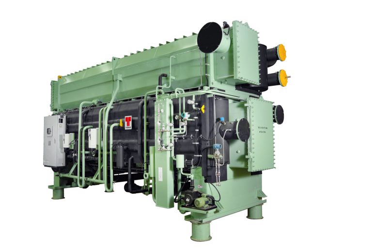
Thermax
Hot water-driven single-effect absorption chillers
Thermax
Hot water-driven single-effect absorption chillers
Thermax
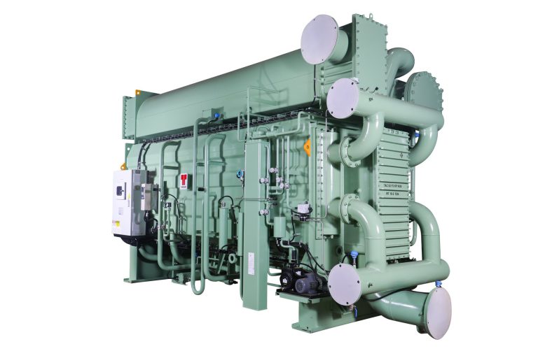
Steam-driven double-effect absorption chillers
Thermax
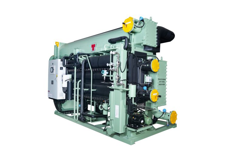
Gas-fired double-effect absorption chillers
Thermax
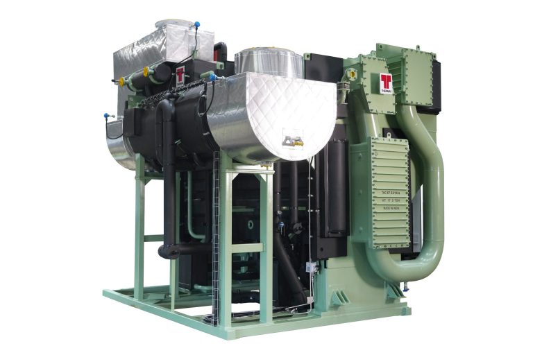
Exhaust gas-driven double-effect absorption chillers