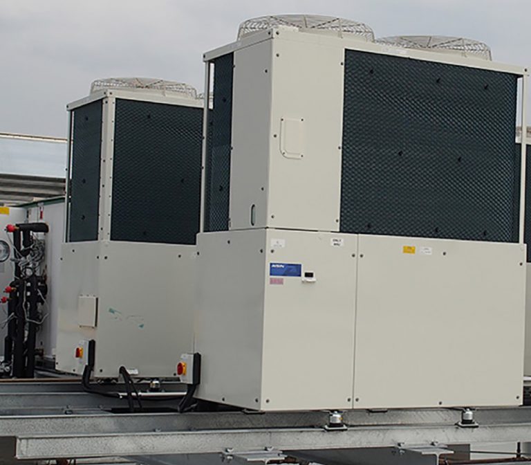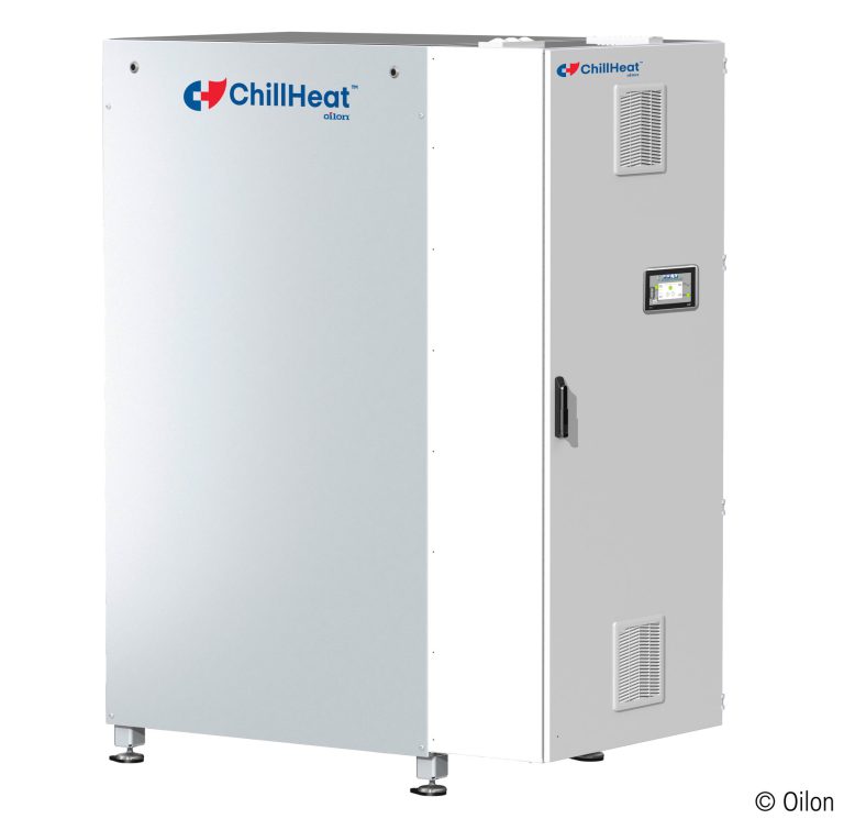
High-temperature heat pumps
Industrial heat pumps that produce hot water up to 120 ºC from waste heat or the air, from 30 to 2,000 kW.
- Cooling capacity
- 29,3 – 184 kW
- Heating capacity
- 30 – 2.000 kW
- Manufacturers
- Oilon and Enerblue
Technology
The compression cycle explained, and how a gas engine-driven compression heat pump works.
The mechanical vapour compression refrigeration cycle is the most widely used and therefore also the best known. In its conventional form, the compressor is driven by an electric motor, and there are several ways of coupling them: open, when the compressor shaft is externally connected to the electric motor; hermetic, when both are contained in a single sealed casing and the mechanical parts are cooled by the returning refrigerant; and semi-hermetic, when the compressor and motor share a closed housing but the motor is cooled conventionally by external means.
The same refrigeration cycle can be driven by a combustion engine running on natural gas or LPG in the vapour phase. In all these cases the configuration is open, with the compressor connected to the end of the engine through a damping device that prevents vibrations from being transmitted.
In the compression cycle, as in the absorption cycle, the cooling effect is obtained because the refrigerant must take from its surroundings the heat it needs to change from liquid to vapour when it enters a space where the pressure is considerably lower than the pressure it was under in the liquid phase. The evaporation (boiling) temperature depends on the pressure, but all liquids need heat to boil and, conversely, their vapour must lose heat to condense back into a liquid.
Figure 1 shows the path of the refrigerant through the compression cycle.
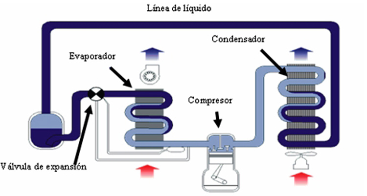
Figure 1. Mechanical compression cycle
The refrigerant gas is compressed in the compressor and discharged at high pressure into the pipe leading to the condenser, where it is cooled and condenses, giving off heat to the cooling medium. Now in the liquid phase and still at high pressure because of the compressor, the refrigerant flows through the pipe known as the liquid line to the expansion valve, which reduces its pressure as it enters the evaporator, where it boils, absorbing heat from its surroundings and therefore cooling them, before finally reaching the suction port, where the cycle begins again. In certain conditions a liquid receiver is fitted between the condenser and the expansion valve to balance the refrigerant volumes, as in the case shown in Figure 1. The high-pressure side runs from the compressor discharge to the expansion valve, while the low-pressure side runs from the outlet of the expansion valve to the compressor suction port.
The fluids used as refrigerants in compression cycles mainly belong to the family of halogenated hydrocarbons. However, the fully halogenated chlorofluorocarbons with no hydrogen atoms in their chemical composition, known as CFCs (fluorine, carbon, chlorine), used until relatively recently (1995), have been banned because they seriously damage the ozone layer and contribute to the greenhouse effect. The phase-out of HCFCs (hydrogen, carbon, fluorine, chlorine) was also planned and regulated for 2015; these are similar to CFCs but contain hydrogen atoms in their molecule, which makes them less stable so that they break down before reaching the stratosphere, giving them a low ozone depletion potential. Finally, there are HFCs (hydrogen, fluorine, carbon), chlorine-free fluorocarbons with hydrogen atoms, which have no ozone depletion potential because they contain no chlorine.
These refrigerants can be pure or blends of different gases, which may or may not be azeotropic. Azeotropic blends are made up of three components and behave like a single pure refrigerant molecule.
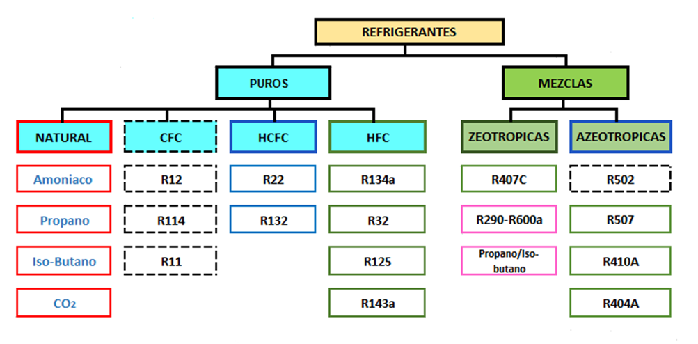
Figure 2. Classification of refrigerants
Non-azeotropic blends are made up of several components, but the blend does not behave like a single pure refrigerant molecule. Systems using these gases must therefore always be charged with liquid, since each gas behaves differently in the gaseous state. These blends also have what is known as glide, which means that at the same pressure the temperature differs depending on whether the refrigerant is gaseous or liquid. This glide can range from 1 to 7 ºC. There are also refrigerants that are inorganic fluids, such as ammonia (NH3), carbon dioxide (CO2) and sulphur dioxide (SO2). Finally, isobutane, known as R-600, which is highly flammable, is also used in some domestic installations. Table 2 shows the distribution of the most commonly used refrigerants.
The heat pump is a thermal machine whose theoretical operating principle was developed by the physicists Clausius, Kelvin and Carnot in the 19th century.
A heat pump can transfer heat from a cold source to a hot sink. In winter it takes heat from the surroundings (cold source) and delivers it into the space to be heated (hot sink). In summer the opposite happens: outside is warmer than inside, so the heat pump extracts heat from the space to be cooled and releases it outdoors.
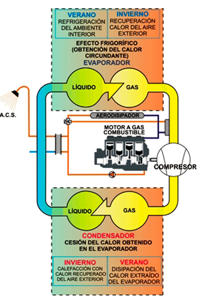
This process requires an additional energy input because, according to the laws of thermodynamics, heat naturally flows from the hot source to the cold one and not the other way round.
Gas-fired HVAC units use the same compression cycle as electric units. The difference lies in the type of motor that drives the compressor: an electric motor in one case and a gas engine in the other.
The main difference is therefore only in the outdoor unit. The heating or cooling distribution system to the indoor units is the same as in conventional electric installations.
The gas installation is also similar to that of other conventional gas appliances, such as a boiler.
One of the main advantages of these units is the waste energy available from the internal combustion engine that drives the compression cycle. Instead of being released to the atmosphere, this energy from engine cooling and exhaust gases is used to produce DHW or to avoid defrost cycles at extreme winter temperatures.
The Spanish Technical Building Code (CTE) considers the recovery of this waste energy for DHW production as an alternative equivalent to installing solar panels, as stated in section HE-4: “the solar contribution may be reduced when that domestic hot water energy input is covered by the use of cogeneration processes or waste energy sources”.
Gas heat pumps are therefore all-in-one HVAC units that can meet a building’s heating, cooling and DHW demand, offering a clear alternative to other technologies such as boilers or electric heat pumps.
Equipment
Industrial heat pumps that produce hot water up to 120 ºC from waste heat or the air, from 30 to 2,000 kW.
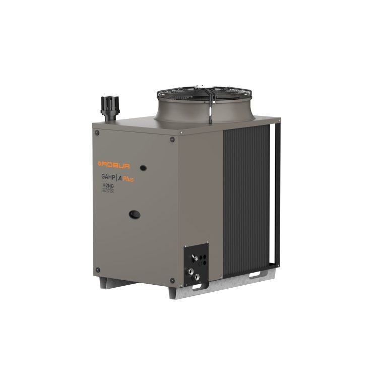
Heat pumps that use natural gas or LPG for heating, DHW and cooling, with minimal electricity demand.
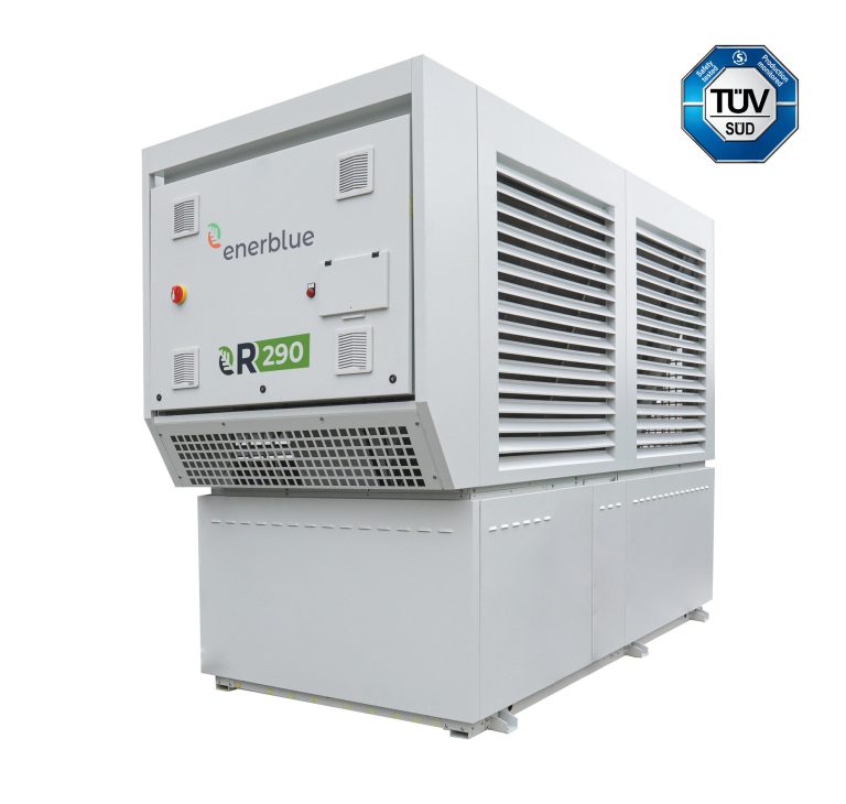
Enerblue air-to-water heat pumps with propane (R290) for heating, cooling and DHW up to 70 ºC, from 26 to 361 kW.
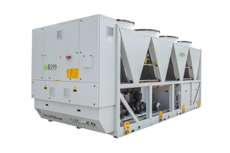
Enerblue water chillers with propane (R290) for air conditioning and industrial processes, from 30.5 to 768 kW.
Applications
Projects
Manufacturers
We'll help you compare absorption, compression and cogeneration based on the energy available and the demand.